
Q36
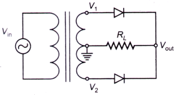
For the rectifier circuit shown in the figure, the sinusoidal voltage (V1 or V2) at the output of the transformer has a maximum value of 10 V. The load resistance RL, is 1 k . If lav is the average current through the resistor RL, the circuit corresponds to a
For the rectifier circuit shown in the figure, the sinusoidal voltage (V1 or V2) at the output of the transformer has a maximum value of 10 V. The load
resistance RL, is 1 k. If lav is the average current through the resistor RL, the circuit corresponds to a
A.
full-wave rectifier with lav = 20/π mA
AnswerB.
half-wave rectifier with lav = 20/π mA
C.
half-wave rectifier with lav = 10/π mA
D.
full-wave rectifier with lav = 10/π mA
Answer: Option A
Solution
Answer: Option A
No explanation is given for this question Let's Discuss on Board