
Q193
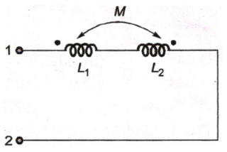
The equivalent inductance measured between the terminals 1 and 2 for the circuit shown in the figure is
The equivalent inductance measured between the terminals 1 and 2 for the circuit shown in the figure is
A.
L1 + L2 + M
B.
L1 + L2 - M
C.
L1 + L2 + 2M
D.
L1 + L2 - 2M
AnswerAnswer: Option D
Solution
Answer: Option D
No explanation is given for this question Let's Discuss on Board