
Q358
The transistor shunt regulator shown in the figure has a regulated output voltage of 10 V, when the input varies from 20 V to 30 V. The relevant parameters for the zener diode and the transistor are: VZ = 9.5, VBE = 0.5 V, β = 99. Neglect the current through RB. Then the maximum power dissipated in the zener diode (PZ) and the transistor (PT) are
The transistor shunt regulator shown in the figure has a regulated output voltage of 10 V, when the input varies from 20 V to 30 V. The relevant parameters for the zener diode and the transistor are: VZ = 9.5, VBE = 0.5 V, β = 99. Neglect the current through RB. Then the maximum power dissipated in the zener diode (PZ) and the transistor (PT) are
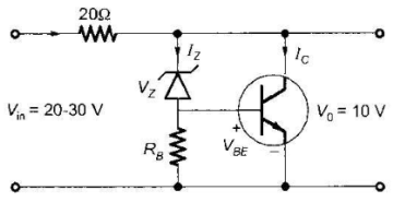
A.
PZ = 75 mW, PT = 7.9 W
B.
PZ = 85 mW, PT = 8.9 W
C.
PZ = 95 mW, PT = 9.9 W
AnswerD.
PZ = 115 mW, PT = 11.9 W
Answer: Option C
Solution
Answer: Option C
No explanation is given for this question Let's Discuss on Board