
Q88
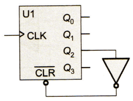
In figure below, U1 is a 4-bit binary synchronous counter with synchronous clear. Q0 is the LSB and Q3 is the MSB of the output. The circuit shown in figure represents a:
In figure below, U1 is a 4-bit binary synchronous counter with synchronous clear. Q0 is the LSB and Q3 is the MSB of the output.
The circuit shown in figure represents a:
The circuit shown in figure represents a:
A.
mod 2 counter
B.
mod 3 counter
C.
mod 4 counter
D.
mod 5 counter
AnswerAnswer: Option D
Solution
Answer: Option D
No explanation is given for this question Let's Discuss on Board