
Q270
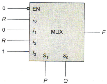
The figure below shows a multiplexer where S1 and S0 are the select lines. I0 to I3 are the input data lines, EN is the enable line, and F(P, Q, R) is the output. F is
The figure below shows a multiplexer where S1 and S0 are the select lines. I0 to I3 are the input data lines, EN is the enable line, and F(P, Q, R) is the output. F is
A.
B.
C.
Answer
D.
Answer: Option C
Solution
Answer: Option C
No explanation is given for this question Let's Discuss on Board