A two port network is described by the relation1 = 2I1 + 3V2 2 = -I1 + 2V2
A. \left[ {\begin{array}{*{20}{c}}
2&3 \\
{ - 1}&2
\end{array}} \right]
B. {\left[ {\begin{array}{*{20}{c}}
{3.5}&{1.5} \\
{0.5}&{0.5}
\end{array}} \right]^{ - 1}}
C. {\left[ {\begin{array}{*{20}{c}}
2&3 \\
{ - 1}&2
\end{array}} \right]^{ - 1}}
D. \left[ {\begin{array}{*{20}{c}}
{3.5}&{1.5} \\
{0.5}&{0.5}
\end{array}} \right]
Select an option to see the answer and solution.
Brune's method of network synthesis is particularly used in
A. RC network
B. RL network
C. RLC network
D. None of these
Select an option to see the answer and solution.
The inductor is a two-terminal energy storage device whose voltage is proportional to the:
A. Integral of the current passing through it
B. Integral of the flux across it
C. Derivative of the current passing through it
D. Derivative of the charge across it
Select an option to see the answer and solution.
Two coupled coils with self inductances of 4 mH and 16 mH are connected in series. The maximum possible value of inductances can be
A. 36 mH
B. 20 mH
C. 28 mH
D. 64 mH
Select an option to see the answer and solution.
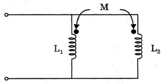
The equivalent inductance of two inductances with mutual coupling in between connected in parallel having the following configuration is given by
A. L 1 + L 2 − 2 M L 1 L 2 + M 2
B. L 1 + L 2 + 2 M L 1 L 2 − M 2
C. L 1 + L 2 + 2 M L 1 L 2 + M 2
D. L 1 + L 2 − 2 M L 1 L 2 − M 2
Select an option to see the answer and solution.
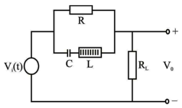
Consider the following circuit
For the above circuit, which one of the following statements is correct? The voltage V
0 is independent of R, if the input signal frequency ω
Select an option to see the answer and solution.
A sinusoidal voltage v(t) = 100sin1000t is applied a pure capacitor of 100 µF. The power is given by
A. 500sin2000t watt
B. 100sin2000t watt
C. 500sin1000t watt
D. 100sin1000t watt
Select an option to see the answer and solution.
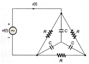
In the circuit shown, if v(t) = 2sin(1000t) volts. R = 1 kΩ and C = 1 µF. Then the steady-state current i(t), in mili amperes (mA), is
A. 3sin(1000t) + cos(1000t)
B. sin(1000t) + cos(1000t)
C. sin(1000t) + 3cos(1000t)
D. 2sin(1000t) + 2cos(1000t)
Select an option to see the answer and solution.
If ID = 10 mA at VD = 1 V at a point of operation, then maximum power dissipation is
A. 1.0 mW
B. 1.0 W
C. 0.1 mW
D. 10 mW
Select an option to see the answer and solution.
Match
List-I with
List-II and select the correct answer using the options given below:
List-I List-II
a. Internal impedance of an ideal current source is
1. Forced response of the circuit
b. For attenuated natural oscillations, the poles of the transfer function must lie on the
2. Natural response of the circuit
c. A battery with an e.m.f. E and internal resistance R delivers current to a load RL. Maximum power transferred is
3. E2 /4 R
d. The roots of the characteristic equation give
4. E2 /2 R
5. Left hand part of the complex frequency plane
6. Right hand part of the complex frequency plane
7. Infinite
8. Zero
A. a-7, b-6, c-3, d-1
B. a-8, b-5, c-4, d-2
C. a-8, b-6, c-4, d-1
D. a-7, b-5, c-3, d-2
Select an option to see the answer and solution.
The time rate of change of a current passed through a 1 mH inductor is 2 mA/s. This means that the voltage across the inductor is:
A. 0.5 × 10⁻⁶ V
B. 0.5 V
C. 2 × 10⁻⁶ V
D. 2 V
Select an option to see the answer and solution.
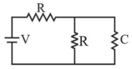
A circuit consisting of two resistors, a capacitor and a battery is shown in the figure. In the steady state, the voltage across the capacitor would be:
A. Zero volts
B. V volts
C. Infinite value
D. 2 V
Select an option to see the answer and solution.
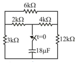
A 18 µf capacitor holding charge of Q coulomb is connected to the circuit at time t = 0 sec.
The time at which the capacitor will be discharged to approximately Q/2.72 coulombs.
A. 68 ms
B. 34 ms
C. 17 ms
D. 2.72 ms
Select an option to see the answer and solution.
A network has 10 nodes and 17 branches. The number of different node pair voltage would be
Select an option to see the answer and solution.
The ideal transformer CANNOT be described by:
A. Z-parameters
B. g-parameters
C. ABCD parameters
D. h-parameters
Select an option to see the answer and solution.
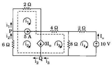
For the given circuit, the currents i
1 and i
3 are
A. i1 = -2.5A and i3 = 3.93A
B. i1 = 7.5A and i3 = 2.5A
C. i1 = 3.93A and i3 = 2.14A
D. i1 = -7.5A and i3 = 3.93A
Select an option to see the answer and solution.
A buffer amplifier has a gain of
A. Infinity
B. Zero
C. Unity
D. Depended upon the circuit parameters
Select an option to see the answer and solution.
A certain network consists of two ideal voltage sources and a large number of ideal resistors. The power consumed in one of the resistor is 4 W when either of the two sources is active and the other is replaced by short-circuit. The power consumed by the same resistor, when both the sources are simultaneously active would be
A. zero or 16 W
B. 4 W or 8 W
C. zero or 8 W
D. 8 W or 16 W
Select an option to see the answer and solution.
Two coils X of 1000 turns and Y of 2000 turns are placed such that 60% of the flux produced by coil X links coil Y. A current of 1 A in coil X produces 0.1 mWb flux. The mutual inductance between the coils is
A. 0.12 H
B. 0.08 H
C. 0.06 H
D. 0.04 H
Select an option to see the answer and solution.
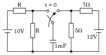
In the network shown in the figure, the switch had remained closed for a long time on the 10 V source side. At time t = 0, it is changed to the 12 V side, then after one time constant, the voltage across 5 Ω in the circuit will be
A. 5 V
B. 5e-1 V
C. 10 V
D. 12 V
Select an option to see the answer and solution.