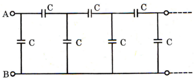
The effective capacitance across AB of the infinite ladder shown in the below figure is
Select an option to see the answer and solution.
The resistances in the higher range are mostly made of:
A. Carbon
B. Aluminium
C. Silicon
D. Germanium
Select an option to see the answer and solution.
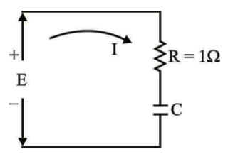
In the series RC circuit shown in the given figure, the rms value of the voltage E is 1 V. If the average power dissipated is equal to 500 mW, then the phase angle between the voltage and current will be
Select an option to see the answer and solution.
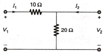
The h-parameters of the circuit shown in the figure are
A. \left[ {\begin{array}{*{20}{c}}
{0.1}&{0.1} \\
{ - 0.1}&{0.3}
\end{array}} \right]
B. \left[ {\begin{array}{*{20}{c}}
{10}&{ - 1} \\
1&{0.05}
\end{array}} \right]
C. \left[ {\begin{array}{*{20}{c}}
{30}&{20} \\
{20}&{20}
\end{array}} \right]
D. \left[ {\begin{array}{*{20}{c}}
{10}&1 \\
{ - 1}&{0.05}
\end{array}} \right]
Select an option to see the answer and solution.
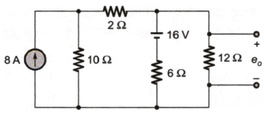
The voltage e
0 in the figure is
Select an option to see the answer and solution.
Thevenin resistance can be found by taking the ratio (o.c = open circuit, s.c = short circuit, Vs = supply voltage, VL = load voltage)
A. I SC V OC
B. I OC V SC
C. I S V S
D. I L V L
Select an option to see the answer and solution.
The permeability and permittivity of a medium are
A. independent of each other
B. related by the velocity of electromagnetic wave
C. related by the Boltzmann's constant
D. None of the above
Select an option to see the answer and solution.
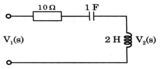
The driving point impedance of the network shown in figure is
A. 10 + 2s
B. 10 + 2s + s 1
C. 10
D. s 1
Select an option to see the answer and solution.
Find equivalent capacitance of the following circuit.
A. 2 3 2 μ F
B. 3 3 1 μ F
C. 4 3 2 μ F
D. 6 μ F
Select an option to see the answer and solution.
Which one of the following is an LC immittance function?
A. Z ( s ) = ( s 2 + 1 ) ( s 2 + 3 ) K s ( s 2 + 4 )
B. Z ( s ) = 3 s 4 + 6 s 2 s 5 + 4 s 3 + 5 s
C. Z ( s ) = ( s 2 + 2 ) ( s 2 + 10 ) K ( s 2 + 1 ) ( s 2 + 9 )
D. Z ( s ) = s ( s 2 + 4 ) 2 ( s 2 + 1 ) ( s 2 + 9 )
Select an option to see the answer and solution.
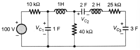
The voltage V
C1 , V
C2 and V
C3 across the capacitor in the circuit in Figure, under steady state, are respectively.
A. 80 V, 32 V, 48 V
B. 80 V, 48 V, 32 V
C. 20 V, 8 V, 12 V
D. 20 V, 12 V, 8 V
Select an option to see the answer and solution.
If the length of a wire of resistance R is uniformly stretched to n times its original value, its new resistance is
Select an option to see the answer and solution.
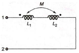
The equivalent inductance measured between the terminals 1 and 2 for the circuit shown in the figure is
A. L1 + L2 + M
B. L1 + L2 - M
C. L1 + L2 + 2M
D. L1 + L2 - 2M
Select an option to see the answer and solution.
In the circuit shown, the switch SW is thrown from position A to position B at time t = 0. The energy taken from the 3 V source to charge the 0.1 µF capacitor form 0 V to 3 V is
Select an option to see the answer and solution.
A transient current in a network is i(t) = 2e-t - e-5t , t ≥ 0, the pole-zero configuration of I(s) is
A. poles : 1, 5 zeros : 9
B. poles : -1, -5 zeros : -9
C. poles : 2, -1 zeros : -1, -5
D. poles : 2, -1 zeros : 1, 5
Select an option to see the answer and solution.
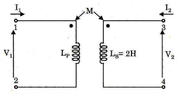
In the transformer shown in the figure below, the inductance measured across the terminal 1 and 2 was 4 H with open terminals 3 and 4. It was 3 H when the terminal 3 and 4 were short circuited. The coefficient of coupling would be
A. 1
B. 0.0707
C. 0.5
D. indeterminate due to insufficient data
Select an option to see the answer and solution.
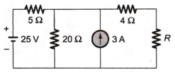
The value of R (in ohms) required for maximum power transfer in the network shown in the figure is
Select an option to see the answer and solution.
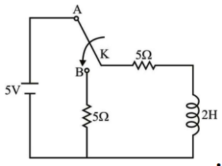
In the following circuit, switch K is thrown from position A to position B at time t = 0, the currenthaving previously reached its steady state:
The current i(t) after switching will be
A. 5e-5t
B. 4e-5t
C. 3e-5t
D. e-5t
Select an option to see the answer and solution.
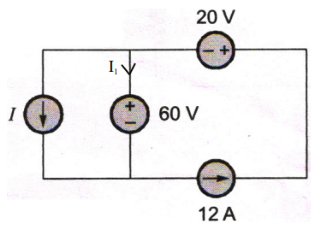
In the interconnection of ideal sources shown in the figure, it is known that the 60 V source is absorbing power.
Which of the following can be value of the current source I?
Select an option to see the answer and solution.
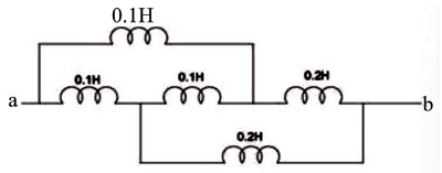
The equivalent inductance across 'ab' for the diagram shown below is:
A. 0.5 H
B. 0.15 H
C. 0.3 H
D. 1 H
Select an option to see the answer and solution.