A signal of 1 kHz is to be amplified, but the circuit board and wires pick up and store 60 Hz component from a nearby electric line. If this component is 40 dB higher than the desired signal, what filter stop band attenuation is necessary to ensure the signal remains 20 dB above the interferer level?
Thermal runaway in a transistor biased in the active region is due to
1. heating of the transistor.
2. change in β due to increase in temperature.
3. change in reverse collector saturation current due to rise in temperature.
4. base emitter voltage VBE which decreases with rise in temperature.
Which of the above statements is/are correct?
An operational amplifier has a slew rate of 100 V/microsecond. For a frequency of 10 MHz, the maximum (peak) value of the sine wave output voltage will be
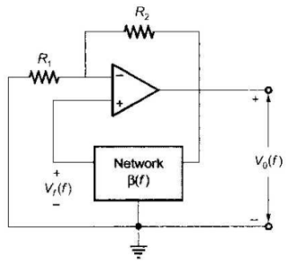
The circuit in the figure employs positive feedback and is intended to generate sinusoidal oscillation.
If at a frequency f0,B(f)=V0(f)Vf(f)=61∠0∘ then to sustain oscillation at this frequency
Consider an ideal long channel nMOSFET (enhancement-mode) with gate length 10 µm and width 100 µm. The product of electron mobility (µn) and oxide capacitance per unit are (Cox) is µnCox = 1 mA/V2. The threshold voltage of the transistor is 1 V. For a gate-to-source voltage VGS = [2 - sin(2t)] V and drain-to-source voltage VDS = 1 V (substrate connected to the source), the maximum value of the drain-to-source current is . . . . . . . .
An n-channel depletion MOSFET has following two points on its ID - VGS curve:
(i) VGS = 0 at ID = 12 mA and
(ii) VGS = -6 volts at Z0 = ∞
Which of the following Q-points will give the highest transconductance gain for small signals?
A full wave rectifier with a centre tapped transformer supplies dc current of 100 mA to a load resistance of 20Ω. The secondary resistance of transformer is 1Ω. Each diode has a forward resistance of 0.5Ω. What are rms values of signal voltage across each half of the secondary as well as dc power supplied to the load?
Two transistors have the same value of α but different gain bandwidth products. One of them is a germanium transistor and the other is a silicon transistor. Both the transistors have similar geometries and base width. The transistor with lower GB product.
A transistor RC coupled amplifier is designed for a voltage and band gain of 20. But a measurement at a particular frequency shows the gain to be only 14. What is the likely phase shift at this frequency?