An OPAMP-based comparator drives an LED, with VF = 1.6V, the current through which is regulated by a 1 kΩ resistor and a silicon diode in series. Assume a ±10V DC voltage is applied as ±VCC respectively to the op-amp. Then find out the current through the LED when the comparator output is +10V.
A common emitter transistor amplifier has a collector load of 10 kΩ. If its hfe = 100 and hie = 2 kΩ (hre ≈ hoe ≈ 0), the voltage amplification of the amplifier is nearly equal to
When the gate-to-source voltage (VGS) of a MOSFET with threshold voltage of 400 mV, working in saturation is 900 mV, the drain current is observed to be 1 mA. Neglecting the channel length modulation effect and assuming that the MOSFET is operating at saturation, the drain current for an applied VGS of 1400 mV is
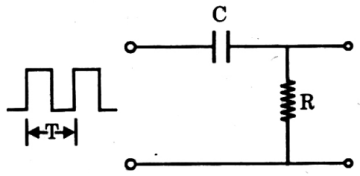
For the circuit given in the figure, consider the following statements:
1. The output VO will consist of a positive and a negative spike if RC << T.
2. The output VO will be similar to Vi if RC >> T.
3. The output will have a higher rise time if RC is made progressively smaller than T.
Of these statements:
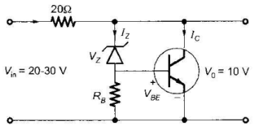
The transistor shunt regulator shown in the figure has a regulated output voltage of 10 V, when the input varies from 20 V to 30 V. The relevant parameters for the zener diode and the transistor are: VZ = 9.5, VBE = 0.5 V, β = 99. Neglect the current through RB. Then the maximum power dissipated in the zener diode (PZ) and the transistor (PT) are