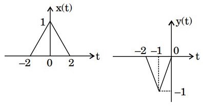
A half-wave rectified sinusoidal waveform has a peak voltage of 10 V. Its average value and the peak value of the fundamental component are respectively given by
Two sequences [a, b, c] and [A, B, C] are related as, \left[ {\begin{array}{*{20}{c}}
A \\
B \\
C
\end{array}} \right] = \left[ {\begin{array}{*{20}{c}}
1&1&1 \\
1&{W_3^{ - 1}}&{W_3^{ - 2}} \\
1&{W_3^{ - 2}}&{W_3^{ - 4}}
\end{array}} \right]\left[ {\begin{array}{*{20}{c}}
a \\
b \\
c
\end{array}} \right] where, W3=ei32π.
If another sequence [p, q, r] is derived as, \left[ {\begin{array}{*{20}{c}}
a \\
b \\
c
\end{array}} \right] =\left[ {\begin{array}{*{20}{c}}
1&1&1 \\
1&{W_3^1}&{W_3^2} \\
1&{W_3^2}&{W_3^4}
\end{array}} \right]\left[ {\begin{array}{*{20}{c}}
1&0&0 \\
0&{W_3^2}&0 \\
0&0&{W_3^4}
\end{array}} \right]\left[ {\begin{array}{*{20}{c}}
{A/3} \\
{B/3} \\
{C/3}
\end{array}} \right]
then the relationship between the sequences [p, q, r] and [a, b, c] is
The signal cos(10πt+4π) is ideally sampled at a sampling frequency of 15 Hz. The sampled signal is passed through a filter with impulse response (πτsin(πt))cos(40πt−2π). The filter output is
The voltage across an impedance in a network is V(s) = Z(s). I(s), where V(s), Z(s) and I(s) are the Laplace transform of the corresponding time functions v(t), z(t) and i(t). The voltage v(t) is
The z-transform X[z] of a sequence x[n] is given by X[z]=1−2z−10.5. It is given that the region of convergence of X[z] includes the unit circle. The value of x[0] is
The transfer function of a system is given by H(s)=s2(s−2)1. The impulse response of the syste is
(* denotes convolution, and u(t) is unit step function)
A periodic signal x(t) has a trigonometric Fourier series expansion x(t)=a0+n=1∑∞(ancosnω0t+bnsinnω0t)
If x(t)=−x(−t)=−x(ω0t−π), we can conclude that
The input to a channel is a bandpass signal. It is obtained by linearly modulating a sinusoidal carrier with a single-tone signal. The output of the channel due to this input is given by y(t)=(1001)cos(100t−10−6)cos(106t−1.56)
The group delay (tg) and the phase delay (tp) in seconds, of the channel are
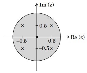
The pole-zero diagram of a causal and stable discrete-time system is shown in the figure. The zero at the origin has multiplicity 4. The impulse response of the system is h[n]. If h[0] = 1, we can conclude
Letx(t) be the input and y(t) be the output of a continuous time system. Match the system properties P1, P2 and P3 with system relations R1, R2, P3, P4. Properties
P1 : Linear but NOT time-invariant
P2 : Time-invariant but NOT linear
P3 : Linear and time-invariant
Relations
R1 : y(t) = t2x(t)
R2 : y(t) = t |x(t)|
R3 : y(t) = |x(t)|
R4 : y(t) = x(t - 5)
Consider a single input single output discrete-time system with x[n] as input and y[n] as output, where the two are related as y\left[ n \right] = \left\{ {\matrix{
{n\left| {x\left[ n \right]} \right|,} & {{\rm{for}}\,0 \le n \le 10} \\
{x\left[ n \right] - x\left[ {n - 1} \right],} & {{\rm{otherwise}}} \\
} } \right.
Which one of the following statements is true about the system?